Most suppliers will tell you their optics are tested. Very few will tell you what that means.
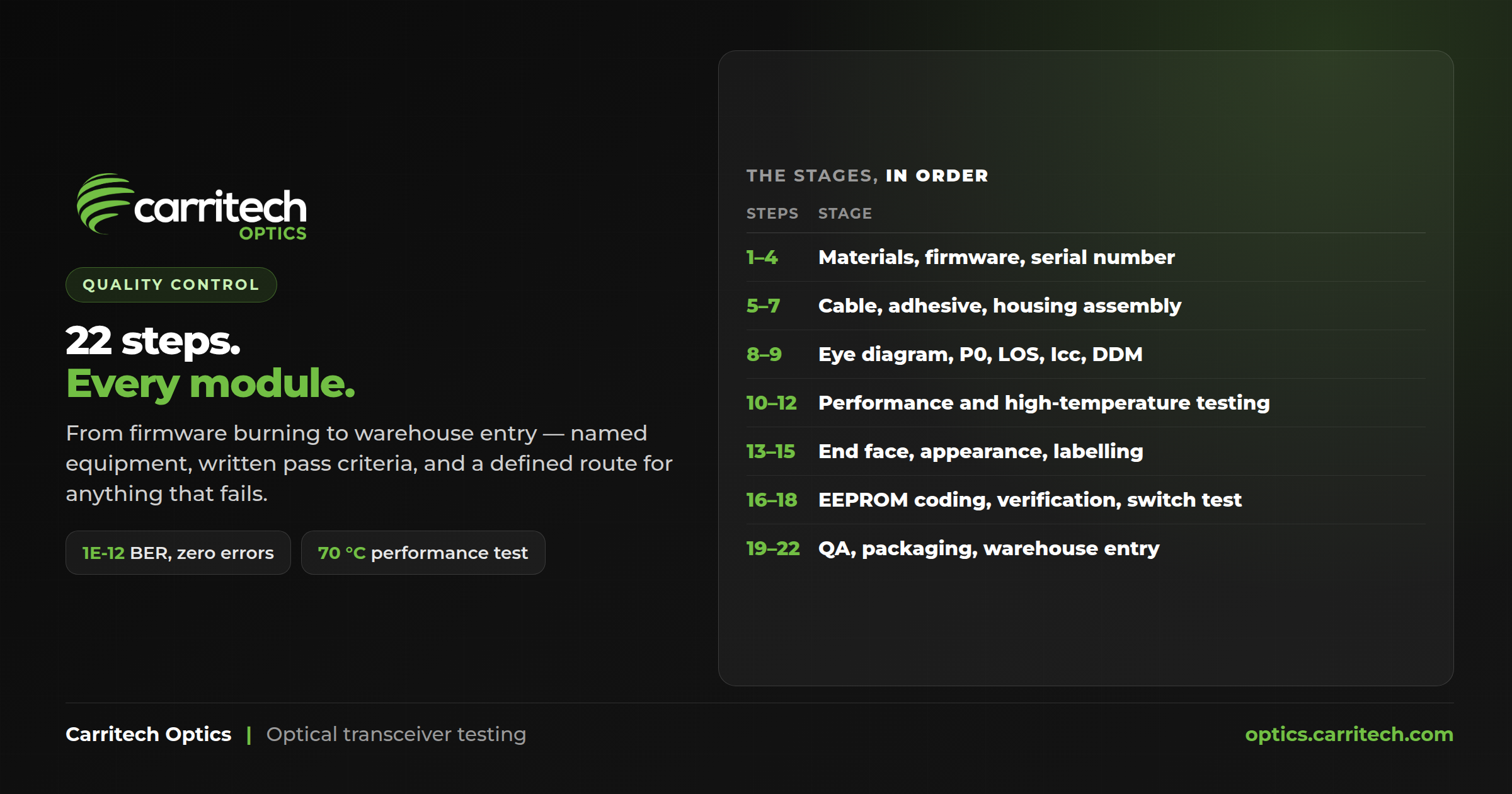
So here is our optical transceiver testing process, in the detail it actually exists in. The modules we supply are built to a documented 22-step quality control process, and this article walks the whole thing — what is checked, what equipment does the checking, what the pass criteria are, and, just as importantly, which steps are done on every single module and which are done on a sample.
That last distinction is the one nobody publishes, and it is the one that tells you the most.
What optical transceiver testing actually means here
One thing to be straight about before the detail: this is a production-line quality control process. It happens where the module is built, on the line that builds it, using the test equipment on that line. It is not a second round of testing performed on receipt in a warehouse.
That matters because “we test every optic” is a claim made by a lot of people who mean very different things by it, ranging from a full optical performance suite down to plugging it in to see whether the light comes on. What follows is a specific, documented process with named equipment, written pass criteria, sampling proportions and a defined route for anything that fails.
The process is documented for the 40G and 100G module lines, which is where the detail below comes from.
The build stages: firmware, serial number, assembly
Optical transceiver testing starts before anything optical is measured. The first seven steps are about getting the right optic built and correctly identified. They matter more than they sound, because most “faulty” third-party optics are not faulty — they are coded wrong, and coding happens here.
- Materials preparation. Check the materials correspond to the bill of materials. 100%, at the start of every shift and after any model change or machine adjustment.
- Firmware burning. Select and burn the corresponding firmware. This is flagged in the process chart as a key process.
- Firmware check. A separate step, on a dedicated firmware detection system, confirming the correct firmware was actually written. Every module, every shift.
- Serial number written.
- Cable installation and adhesive dispensing. Also a key process. The written criteria are specific: the adhesive must be properly covered, must not overflow, and the cure is 30 seconds of irradiation.
- Initial optical engine power test. Key process. The optical engine’s power output must fall within range before it goes any further — so a bad engine is caught before anyone spends time assembling a housing around it.
- Housing and optical engine assembly. The engine seats on the base with the right tension, the pull ring is checked for normal opening and closing, the position of the thermal conductive adhesive is checked, and the appearance is inspected.
Step 7’s thermal adhesive check is worth pausing on. It is the difference between a module that dissipates heat into its cage as designed and one that runs hot in a dense switch — which is a fault that does not show up on a bench and does show up in a warm rack six months later.
The optical transceiver testing that decides whether it ships
Steps 8 to 12 are where the module either performs or does not.
8 — Eye diagram debugging. Run on direct current with a BERT, thermometer, fixed light source, test board, optical power meter, optical attenuator and fibre patch cord. The written criterion is that extinction ratio and the other parameters meet requirements. Judged by the test software, not by eye. Every module, every shift.
9 — Optical module debugging. A key process. The parameters watched here are P0 (output power), LOS (loss of signal), Icc (supply current) and DDM calibration.
That DDM calibration step deserves a note. Digital diagnostic monitoring is how the module reports its own transmit power, receive power, bias current and temperature back to your switch — the numbers you read in the interface table. SFF-8472, the specification that defines DDM, allows ±3 dB on optical power. Calibrating it on the line is what keeps those readings meaningful, and an uncalibrated module reporting nonsense diagnostics is worse than one reporting nothing, because it sends you looking in the wrong place.
10 — Initial performance testing. The stated criteria: 70 °C, a bit error rate of 1E-12, and zero bit errors, with P0, ER and DDM monitoring within requirement. Every module, every shift.
That 1E-12 figure is not arbitrary — it is the bit error ratio objective IEEE 802.3 sets for Ethernet PHYs, so the module is being held to the same number the standard holds the link to.
11 — Fibre transmission testing. At normal temperature, 25 °C, for 60 seconds, again at 1E-12 with zero bit errors, with P0, ER and DDM monitored throughout. Every module, every shift.
12 — High temperature testing. And here is the first honest caveat: this step runs on a 5% sample, not on every module.
Where optical transceiver testing is sampled, and where it is not
This is the section most testing pages leave out, so it is worth being direct.
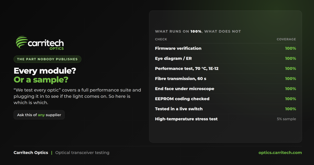
Run on 100% of modules: firmware check, eye diagram debugging, initial performance testing at 70 °C, fibre transmission testing, end face cleaning inspection, appearance cleaning and inspection, EEPROM programming, EEPROM and serial number verification, switch testing, packaging inspection, and the finished-goods check on entry to the warehouse.
Run on a sample: high temperature testing at 5%. Firmware burning, serial number writing, adhesive dispensing, initial power testing, housing assembly, module debugging, labelling and QA appearance inspection carry a 5–20% in-process quality control sample twice a day, on top of a 100% operator check at each of those stations. Finished-goods outer-box inspection is a QA sampling inspection on a C=0 acceptance basis — meaning the sample is rejected on a single defect.
So the accurate sentence is: every module is performance tested, and a proportion of them are additionally stress tested at high temperature. Not the same claim, and we would rather publish the real one.
Cleaning, coding and the switch test
The last stages of optical transceiver testing are the ones that decide whether a good module arrives in usable condition.
13 — End face cleaning inspection, using a microscope fibre end-face inspector, end face cleaner, dust-free paper, alcohol and cotton swabs. Every module.
This step is more important than it reads. Contamination on a fibre end face is the single most common cause of loss on an optical link, and the criteria most inspection kits grade against come from IEC 61300-3-35. An optic that leaves the line with a dirty end face will look like a marginal link at the far end, and nobody will suspect the module.
14 — Appearance cleaning and inspection.
15 — Labelling. The label must be undamaged and attached within the specified range.
16 — EEPROM programming. The module’s code file is written with the specific requirements for the order.
17 — EEPROM and serial number verification. The check reads back manufacturer, part number, serial number, date, threshold, PAGE0 and PAGE1 and confirms they match the order.
This is the coding step, and it is the one that decides whether an optic works in your switch. A switch reads that EEPROM to identify the module, and on many platforms uses what it reads to choose a link-layer setting such as FEC mode. Get it wrong and the module either is not recognised or is recognised as something it is not — which is a link that stays down while logging nothing useful about the transceiver.
18 — Switch testing. The module goes into an actual switch, and the checks are module locking and unlocking, link establishment, and EEPROM information. Judged by the switch itself.
QA, packaging and warehouse entry
The final four steps sit outside optical transceiver testing proper — they are about the module surviving the journey.
19 — QA appearance sampling inspection, at 5–20%, twice a day, by the quality department rather than by production.
20 — Packaging and labelling, with vacuum packaging, an appearance check, and label and quantity verification.
21 — Finished appearance and outer box QA inspection. Packing appearance, model, standards, label information and quantity, on the C=0 basis described above.
22 — Finished goods storage. Order quantity, product information and packaging integrity checked on entry, on every box.
And when something fails, at any of the 22 steps, the documented route is the same: the unit is isolated and identified, a nonconforming product disposal form is raised, and a corrective and preventive action report follows. Failures are not simply set aside — they generate a record, which is what makes a recurring fault visible rather than a series of unrelated one-offs.
What we do not claim
Being specific about what our optical transceiver testing does means being equally specific about what it does not, so:
- We do not thermal-cycle every module. High temperature testing is a 5% sample. Steps 10 and 11 test every module at 70 °C and at 25 °C respectively, which is not the same as cycling it.
- We do not test to −40 °C. The documented temperatures in this process are 70 °C and 25 °C. Modules specified for industrial temperature ranges are a different specification, and where a deployment needs one it should be ordered as one.
- We do not re-test on receipt. This is production-line quality control at the point of manufacture.
- We do not publish a mean time between failures figure, because we do not have one derived from our own field data, and quoting somebody else’s would be meaningless.
What to ask any supplier about their optical transceiver testing
If you are evaluating a supplier — us or anyone else — these are the questions that separate a real process from a claim:
- Which steps run on 100% of modules and which run on a sample? Anyone with a real process can answer this immediately, with numbers.
- What is the bit error rate criterion, over what duration, at what temperature? “We test for errors” is not an answer. 1E-12 with zero errors at 70 °C is.
- Is DDM calibrated, and against what? If it is not, every diagnostic reading you take from that module afterwards is decoration.
- Is the fibre end face inspected under a microscope before packing? This is cheap to do, expensive to skip, and invisible until it is a fault.
- Does the module go into an actual switch before it ships? Coding faults do not show up any other way.
- What happens to a unit that fails? If the answer is not “it is isolated, recorded, and the failure is analysed”, the process has no feedback loop.
Checking a part before you order it
Optical transceiver testing tells you the module was built correctly. It does not tell you whether it is the right module — that is a coding and specification question, and it is answered before you order rather than after.
You can check any OEM part number against a compatible equivalent and see form factor, reach, media and connector side by side. If you are working from a quote or a bill of materials rather than a single part, send us the list and we will price it line by line.
Background reading that is not ours: the Fiber Optic Association on optical loss testing, and the TIA Fiber Optics Tech Consortium on which Ethernet standard defines what.