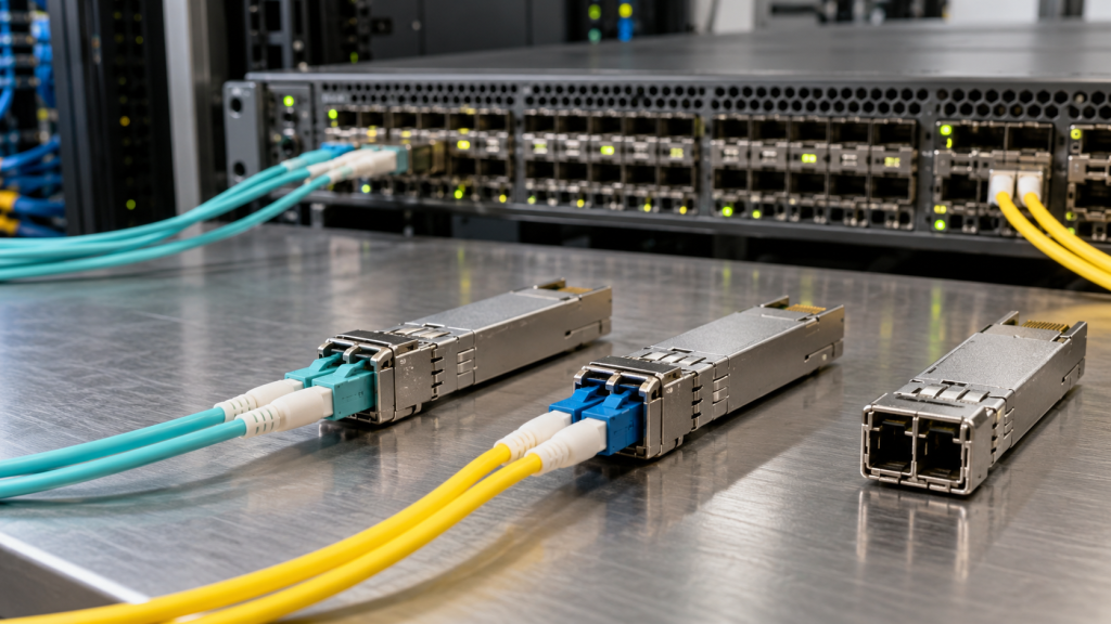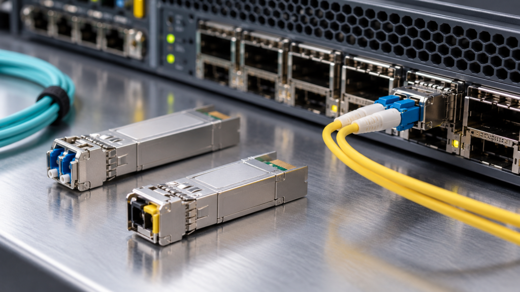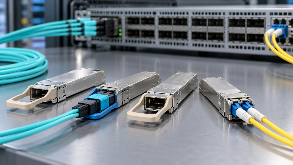
Here is a link that is working perfectly: a 400G port correcting something in the order of a hundred thousand bit errors every second, continuously, for years. Nothing is wrong with it. Nothing needs replacing. That error rate is not a symptom — it is the design point.
Forward error correction is the reason modern optical links work at all, and it is also the reason a lot of perfectly good modules get returned. Once FEC is in the path, the counters you were trained to read mean something different, the troubleshooting instinct of “errors equal fault” stops being true, and the module in the cage is no longer the component doing the correcting.
This article explains what forward error correction actually does, which FEC applies at which speed, where it physically lives, how to read a FEC-protected link properly, and what it costs you in overhead, latency and power.
The short version
FEC sends redundant information alongside your data so the receiver can repair errors without asking for a retransmission. In exchange for spending a few percent of the line rate on parity, you buy several decibels of optical margin — margin you then spend on cheaper lasers, longer reach, hotter racks, dirtier connectors and faster signalling.
Below 25G per lane that trade was optional. From 25G per lane upwards it is not. PAM-4 signalling, which is how every 50G-per-lane and faster interface works, puts three decision thresholds where NRZ had one, and the raw error rate that comes off the receiver is far too high to use unprotected. FEC is what turns that raw signal into an error-free link.
How Reed-Solomon FEC works, in one section
Every FEC used in mainstream Ethernet and Fibre Channel today is a Reed-Solomon code. The mechanism is worth understanding because the vocabulary on your switch CLI comes straight out of it.
- Symbols, not bits. The data stream is chopped into 10-bit symbols. RS codes correct whole symbols, so one bad bit and ten consecutive bad bits inside the same symbol cost exactly the same to repair. This is why FEC copes well with short bursts of errors and badly with long ones.
- Codewords. Symbols are grouped into fixed-length codewords. The notation RS(n,k) means a codeword of n total symbols carrying k symbols of your data, with the remaining n−k symbols as parity.
- Correction capacity. An RS code can repair up to (n−k)/2 symbol errors per codeword. Below that threshold, every error is fixed and the link is clean. Above it, the decoder either fails to correct the codeword or — rarely — mis-corrects it.
- The cliff. That threshold behaviour is the single most important operational property of FEC. Performance does not degrade gracefully. A link sits perfectly clean while errors stay under the limit, then falls apart very quickly once they do not. There is almost no middle ground, which is why FEC-protected links tend to fail suddenly rather than get gradually worse.
Two codes carry nearly all of the traffic in the world. RS(528,514) carries 514 data symbols in a 528-symbol codeword, corrects up to 7 symbol errors, and costs about 2.7% in overhead. RS(544,514) keeps the same payload in a longer codeword, corrects up to 15 symbol errors, and costs about 5.8%. The second is roughly twice as strong as the first and is what everything from 50G per lane upwards uses.
The FEC ladder, by speed
Ethernet FEC is defined in clauses of IEEE 802.3, and engineers refer to the clause numbers more often than the code names. Worth knowing both.
| Clause | Code | Overhead | Where it applies | Optional? |
|---|---|---|---|---|
| 74 ("FC-FEC", BASE-R) | Fire code (2112, 2080) | ~1.5% | 10G and 25G backplane and copper; optional on 25G optical | Yes |
| 91 ("RS-FEC", KR4) | RS(528,514) | ~2.7% | 100G over 4 × 25G lanes | Mandatory on most 100G PMDs |
| 91 ("KP4") | RS(544,514) | ~5.8% | Higher-loss 100G electrical channels | Mandatory where specified |
| 108 | RS(528,514) | ~2.7% | 25G single lane | Mandatory on 25GBASE-SR and similar |
| 134 | RS(544,514) | ~5.8% | 200G and 400G | Mandatory |
| 161 / 162 and later | RS(544,514) | ~5.8% | 50G per lane, 100G per lane, 800G and 1.6T | Mandatory |
Three things to take from that table.
- 25G is the awkward generation. It is the only speed where FEC is genuinely a choice, and therefore the only speed where the two ends can be configured to disagree. A 25G link that will not come up, with healthy optical power at both ends, is very often a FEC mismatch rather than an optics fault. Our comparison of SFP+ and SFP28 optics covers the rest of what changes at 25G.
- 100G is where RS-FEC became the default, arriving with the 4 × 25G generation that followed IEEE 802.3ba‘s original ten-lane 100G. Clause 91 came out of IEEE 802.3bj, finished in 2014 — it was written for backplanes and copper cable, and optical PMDs inherited it.
- From 200G upwards there is nothing to configure. RS(544,514) is mandatory, both ends run it, and the FEC question disappears from your change control. What replaces it is the counter-reading question in the next section.
The point almost everyone gets wrong: FEC is in the host, not the module
On a standard Ethernet link, forward error correction is implemented in the host — the switch ASIC or the line card PHY. It sits in the PCS, below the MAC and above the electrical interface to the cage. The transceiver is downstream of it, and from FEC’s point of view the module, the fibre and the far-end module are all just one noisy channel in the middle.
Which has consequences that come up constantly in support conversations:
- You cannot buy a module with better FEC. A retimed pluggable does not choose or implement the Ethernet FEC. Two modules of the same PMD type present the same interface to the same host FEC. If a link is failing for FEC reasons, changing brand of optic does not change the FEC.
- Both ends must agree, and the host decides. At 25G this is configuration. Above it, it is fixed by the PMD. Either way the setting lives on the switch, not in the EEPROM.
- FEC statistics are host statistics. Corrected and uncorrected codeword counts come from the host PHY. They are not in digital diagnostics, and no amount of reading the module will produce them — a distinction worth keeping straight alongside the values that DDM does give you, covered in our guide to spotting a failing fibre link before it drops.
- Coherent modules are the exception. A coherent pluggable has a DSP inside it running its own, much stronger FEC on the line side — and that one really is a property of the module. More on that below.
What the module genuinely does affect is the raw error rate feeding into the FEC: receiver sensitivity, transmitter extinction ratio, the quality of the electrical interface to the host. A module can absolutely be the reason a link runs out of FEC headroom. It is just never the thing doing the correcting.
How to actually read a FEC-protected link
Four counters matter, and the order matters more than the numbers.
- Uncorrectable codewords. The only counter that represents damage. A codeword the decoder could not repair becomes lost data and, at the MAC layer, a dropped frame. This number should be zero. Any sustained non-zero value is a real fault, and this is what you escalate on.
- Corrected codewords, or pre-FEC error rate. This is work being done, not harm being done. Judge it by trend, not by absolute value. A 400G link steady at a pre-FEC bit error ratio of 10−6 is comfortable. The same link drifting from 10−6 toward 10−4 over a fortnight is telling you something is degrading and you have weeks, not months.
- Symbol error distribution per lane. Most platforms break errors down by lane. One hot lane on a parallel module points at one fibre, one connector or one MPO position — see MPO polarity explained for how easily that happens. Errors spread evenly across every lane point at the module, the host channel or temperature.
- MAC-layer FCS errors. If these are climbing while uncorrectable codewords are zero, your problem is somewhere other than the optical link.
The headline rule: a non-zero corrected-error count is not a fault, and a zero one is not proof of health. A link can sit one decibel from the FEC cliff and report nothing uncorrectable at all, right up until a warm afternoon pushes it over. Which is exactly why the pre-FEC trend is the useful number — it is the only visibility you have into how much margin is left.
How much error can FEC actually absorb?
For RS(544,514) the figures are in the public IEEE 802.3 record, and they are more interesting than a single threshold suggests. Analysis presented to the 802.3cd task force puts the tolerable input bit error ratio at about 3.8 × 10⁻⁴ when errors arrive randomly — but at only 2.5 × 10⁻⁵ when the errors arrive in bursts through a 2:1 bit-multiplexed channel. Same code, same target output, a factor of fifteen difference in what it will take.
That gap is the practical lesson about Reed-Solomon codes. Because correction is counted in symbols per codeword, errors that clump together into few symbols are cheap and errors that scatter across many symbols are expensive. Anything that correlates errors — PAM-4 decision errors, bit multiplexing, pattern-dependent jitter, a reflection — eats FEC budget faster than its raw bit error rate suggests. It is also why precoding exists in the faster PMDs: it exists specifically to break up the error patterns PAM-4 receivers naturally produce.
For RS(528,514) the commonly quoted figure is around 5 × 10⁻⁵ — roughly an order of magnitude less tolerant than RS(544,514) under random errors, which is the whole reason the longer codeword was adopted for the faster interfaces.
What FEC costs
Line rate
Parity has to be transmitted, so the signalling rate rises above the data rate. This is why a 400G interface does not run at 400 gigabaud-equivalents of payload, and why the raw rates in a datasheet never match the round numbers in the product name. It is also, incidentally, part of why Fibre Channel’s speed names look odd next to Ethernet’s — covered in our guide to Fibre Channel transceivers.
Latency
A decoder cannot correct a codeword until it has the whole codeword, so latency scales with codeword length. For most applications this is irrelevant. For high-frequency trading, some HPC fabrics and tightly-coupled storage it is not, which is why the Ethernet Technology Consortium publishes a low-latency FEC specification built on RS(272,258) — half the codeword length of RS(544,514), with the expectation that decode latency scales down accordingly. It is a niche option, it needs support at both ends, and it trades correction strength for responsiveness. Most networks should not go looking for it.
Power
FEC encode and decode is continuous digital signal processing and it is not cheap. On a retimed pluggable the DSP — FEC engine included — is commonly around half the module’s total draw, which is why removing it is the central idea behind linear pluggable optics. The numbers are in our guide to optical transceiver power consumption.
FEC outside Ethernet
Three other worlds use FEC differently, and if your estate spans them the differences matter.
Fibre Channel
Storage fabrics follow the same pattern a generation behind Ethernet. 16GFC treats FEC as optional and usually runs without it on optical links. 32GFC mandates RS(528,514). 64GFC and 128GFC mandate RS(544,514) for their PAM-4 signalling. The standards come from the INCITS Fibre Channel Technical Committee, and the practical consequence is that the FEC-mismatch fault class that plagues 16G disappears entirely at 32G and above. Our Fibre Channel transceivers guide and the 16G, 25G and 32G overview cover what else changes.
Optical transport
OTN has used FEC since long before Ethernet needed it. ITU-T G.709 specifies an RS(255,239) code in the OTU frame, carrying about 6.7% overhead — a generous budget by Ethernet standards, reflecting that transport links have always been longer, noisier and more expensive to re-engineer than a data centre interconnect.
Coherent pluggables
Here FEC genuinely is a property of the module, and it is the single biggest differentiator between coherent variants. 400ZR uses a concatenated FEC; OpenZR+ uses a stronger open FEC to buy the extra reach. Same form factor, same client interface, different coding — and not interoperable with each other, which is the point made at length in 400ZR vs OpenZR+. The host-side management that exposes all of this runs through the OIF’s Common Management Interface Specification. If you are putting coherent optics into router ports, start with data centre interconnect e tunable transceivers in DWDM networks.
Does FEC hide a bad optic?
This question comes up whenever somebody is weighing compatible modules against OEM, so it is worth answering directly: yes, and that is a problem for everybody equally.
FEC will absorb a marginal module, a dirty connector, an over-length run or a bent patch lead and present you with a clean link. It is doing its job. But it is spending margin you were meant to be holding in reserve, and the symptom only appears when something else — a hot day, an added patch panel, an ageing laser — takes the last of it. That is the mechanism behind the single most common optical fault we see: a link that worked for two years and then stopped, with nothing having changed.
The defence is not to distrust FEC. It is to know how much headroom you have, which means two things: working the optical link budget properly rather than trusting the datasheet distance, and trending pre-FEC error rate so that a degrading link announces itself. Clean end faces are the cheapest margin available anywhere — see fibre optic connector cleaning. And buying modules whose optical performance is measured rather than assumed is why Carritech tests every one before despatch, which the 22 checks a module passes sets out.
Eight practical rules
- Escalate on uncorrectable codewords, investigate on trends. Corrected errors are the system working.
- Trend pre-FEC error rate per port. It is the only measure of remaining margin you get, and it is where a failing link shows up first.
- At 25G, check FEC configuration at both ends before you touch the optics. It is the most common cause of a 25G link that will not establish.
- Do not judge a 32G or 400G link by 10G standards. A busy corrected-error counter is normal and expected.
- Look at per-lane distribution before you swap anything. One bad lane is a fibre or connector problem; all lanes is a module, channel or thermal problem.
- Do not expect a different module to change the FEC. On standard Ethernet links the FEC is in the host.
- Do not assume headroom. A clean link may have none. Work the budget.
- Treat coherent FEC as a compatibility attribute. 400ZR and OpenZR+ do not interoperate, and the FEC is why.
Modules measured against the margin they need
FEC only has margin to spend if the optics put it there in the first place. Carritech Optics supplies the full range of compatible optical transceivers from 155M to 1.6T — 25G SFP28, 100G QSFP28, 400G QSFP-DD, 800G OSFP e 1.6T OSFP — plus the 32G Fibre Channel modules where FEC became mandatory on the storage side.
Every module is measured against its specification before despatch — our transceiver testing process covers receiver sensitivity, extinction ratio and optical power, which are precisely the parameters that decide how much error your FEC has to absorb. Every module is coded for the platform it is going into (transceiver coding explained), and everything carries a garantia vitalícia, with UK and EU stock and support behind it. For the usual procurement questions, compatible optical transceivers vs OEM e do third-party optical transceivers void your warranty? answer them straight.
Chasing a link that corrects more than it should? Send us the port, the module part numbers and the FEC counters and we will tell you what we think is happening — or use the compatibility checker to find the tested equivalent of what is in the cage, upload a whole part-number list, or request a quote.