Every jump up the Ethernet speed ladder gets described the same way: twice the bandwidth in the same footprint. It is true of 1.6T, but it is also the least interesting thing about it.
The change that actually matters is underneath. 1.6T is the first mainstream generation built on 200 Gigabits per second per lane, and doubling the lane rate rather than adding more lanes has consequences that reach beyond the module itself — into your fibre plant, your connector inventory, your rack power budget and your cooling design.
This guide covers what 1.6T optical transceivers are, what the standards actually specify, and the practical questions worth answering before you commit to a deployment.
What is a 1.6T optical transceiver?
A 1.6T optical transceiver delivers 1.6 Terabits per second — 1,600 Gigabits — through a single pluggable module.
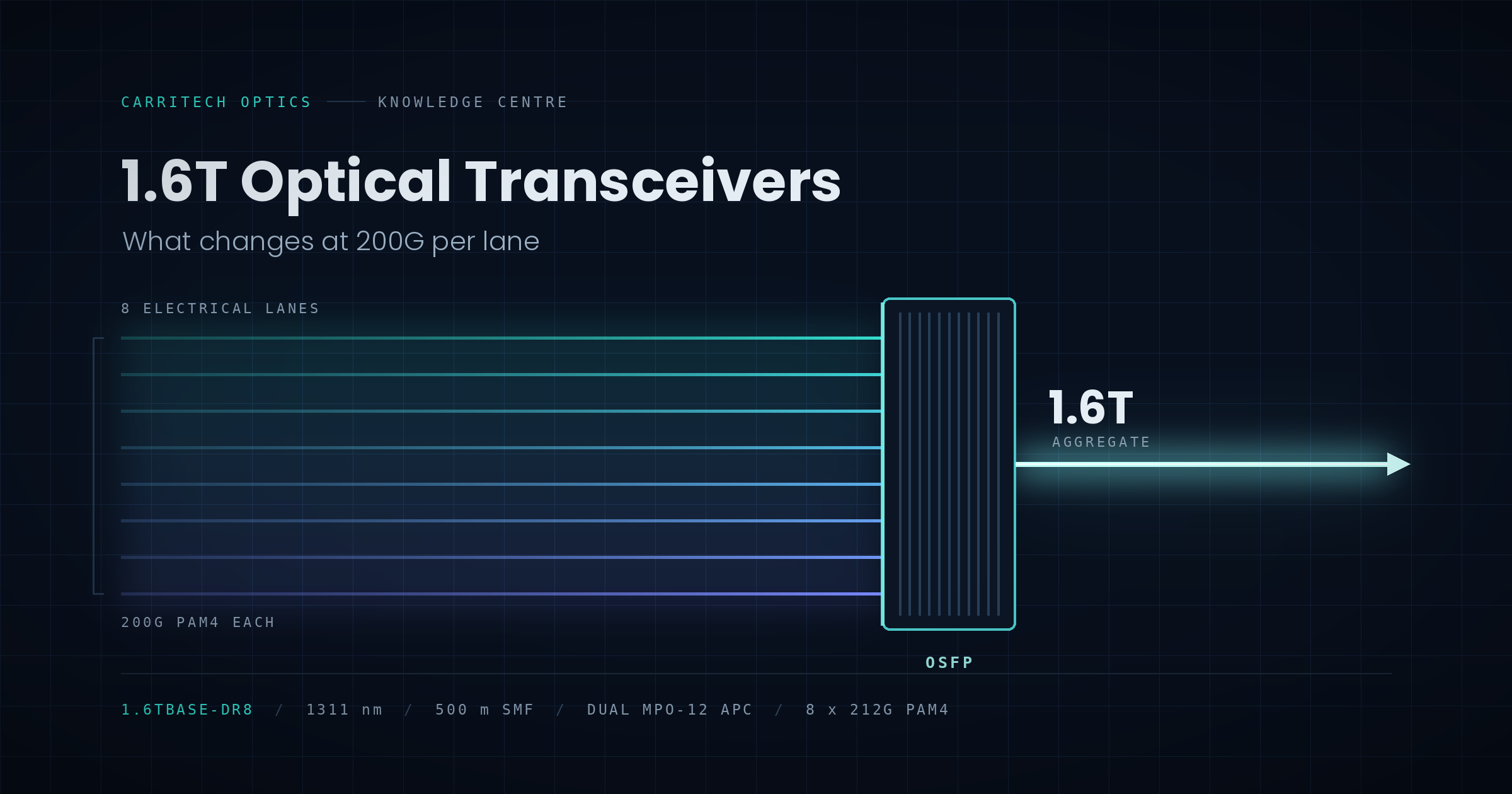
It gets there using eight lanes running at roughly 200G each, using PAM4 (four-level pulse amplitude modulation) signalling at approximately 106 Gigabaud. You will often see the lane rate quoted as 212G rather than 200G; that figure includes forward error correction overhead, and both numbers describe the same thing.
The contrast with 800G is the point. An 800G module built to the earlier generation uses eight lanes at 100G. A 1.6T module uses eight lanes at 200G. Same lane count, same electrical interface width, double the throughput. That is what allows 1.6T to slot into comparable faceplate real estate rather than demanding a wider module.
Doubling the lane rate instead of the lane count also reduces pin count per bit, simplifies PCB routing on the host board, and improves efficiency per bit carried. It is a cleaner scaling path than simply widening the interface — but it puts far more pressure on signal integrity, which is why the surrounding standards work has been so extensive.
The standards picture: IEEE 802.3dj
The relevant Ethernet work is IEEE P802.3dj, the task force defining MAC parameters, physical layer specifications and management parameters for 200G, 400G, 800G and 1.6T operation.
You can follow the project directly through the IEEE 802.3dj Task Force pages, which publish drafts, presentations and ballot results in the open. As of mid-2026 the amendment has progressed through multiple ballot recirculations and is in the closing stages of the standardisation process, with completion anticipated during 2026. Modules shipping today are built to the mature late drafts — a normal and well-established pattern in optical networking, but one worth understanding when you evaluate interoperability claims.
The 1.6T optical interfaces defined for parallel single-mode fibre are:
| PMD | Atteindre | Fibre | Notes |
|---|---|---|---|
| 1.6TBASE-DR8 | 500 m | Parallel single-mode (16 fibres) | Tight channel insertion loss allowance |
| 1.6TBASE-DR8-2 | 2 km | Parallel single-mode (16 fibres) | Uses concatenated inner/outer FEC |
Alongside these sit 1.6TBASE-CR8 for copper cable and 1.6TBASE-KR8 for backplanes, plus the 1.6TAUI-8 electrical interface that connects the module to the host.
Two other bodies matter here. The Optical Internetworking Forum develops the electrical interface specifications and maintains CMIS, the management interface that 1.6T modules use for diagnostics and control. The OSFP MSA defines the mechanical and thermal specifications for the form factor itself, including the OSFP1600 variants used at this speed. Between them, IEEE, OIF and the OSFP MSA are the sources worth checking when a vendor makes a compliance claim.
For a broader view of where 1.6T sits on the roadmap, the Ethernet Alliance Ethernet Roadmap is the clearest single reference in the industry.
Form factors: OSFP, OSFP-XD and QSFP-DD
OSFP is the dominant form factor for 1.6T. It has the electrical lane count, the mechanical volume and — critically — the thermal headroom that 200G-per-lane optics require.
Two OSFP variants come up repeatedly:
- OSFP1600 (flat top / integrated heat sink) — the module carries its own heat sink. Common in switch and router applications.
- OSFP1600-RHS (riding heat sink) — the module has no integrated heat sink and relies on a cage-mounted one. Chosen where the system thermal design is built around it.
These are not interchangeable at the point of installation. Check which your platform’s cages expect before ordering.
OSFP-XD takes a different route, doubling the electrical lanes from 8 to 16. It appears mainly in designs targeting higher densities or forward compatibility toward 3.2T.
QSFP-DD does exist in 1.6T variants, but the form factor’s smaller thermal envelope makes it a harder engineering problem at this power level. OSFP remains the safer default for most deployments.
The fibre and connector question — check this first
This is where 1.6T deployments most often hit an unexpected cost, and it is worth resolving before anything else.
1.6TBASE-DR8 needs sixteen fibres — eight transmit, eight receive. That can be presented in two ways:
- A single MPO-16 connector
- Dual MPO-12 APC connectors
If your existing structured cabling is built around MPO-12, a module presented as dual MPO-12 APC will drop into that plant far more easily than one requiring MPO-16. If your plant is MPO-16, the reverse applies. Getting this wrong means either adapter panels or a cabling replacement — neither cheap, and neither something you want to discover during a change window.
Two further details are easy to overlook:
APC versus UPC. Parallel single-mode 1.6T interfaces use angled physical contact (APC) connectors. Mating an APC connector to a UPC one produces a poor connection and significant loss. Your patch cords need to match.
Insertion loss headroom. The 500 m DR8 interface is specified with a notably tight channel insertion loss allowance — in the region of 3 dB in the draft specifications. That is not much budget once you account for patch panels, splices and connector wear across a real installation. If you are pushing toward the reach limit through several patching points, model the link before you buy. Our article on why optical link budget matters when choosing transceivers covers the calculation in full, and the principles apply directly here.
You can source matched MPO and LC patch cords alongside the modules themselves.
Breakout: 1.6T as two 800G links, or four 400G
One of the strongest practical arguments for 1.6T has nothing to do with running 1.6T end to end.
A 1.6T DR8 module can be configured as 2 × 800G (2×DR4) ou 4 × 400G, giving you a single high-density switch port that feeds multiple lower-speed devices. In a leaf-spine fabric, that means one port and one cable run serving several downstream connections.
The result is fewer switch ports consumed, fewer cable runs and simpler upstream capacity planning. For many networks, breakout is the reason to buy 1.6T at the spine even when nothing downstream needs 1.6T yet — it collapses port count while leaving room to grow into the full rate later.
If you are working through this kind of staged upgrade, our 800G transceiver range et 400G transceiver range cover the downstream side of the same design.
Power and thermal: plan the rack, not just the port
A 1.6T OSFP module typically dissipates around 25 W. Individually that is manageable. Aggregated across a densely populated switch, it is a rack-level design constraint.
Three things to check before deployment:
Cooling capacity. A fully populated 1.6T switch generates substantially more heat than the 800G equivalent it replaces. Verify that rack airflow and room cooling can absorb it, particularly in older facilities designed around lower densities.
Power distribution. PDU circuits sized for a previous generation of switching may not have headroom for a full 1.6T chassis. This is a straightforward calculation, and a much cheaper problem to find on a spreadsheet than in production.
Thermal derating. Optical modules run at reduced performance, or shut down, when they exceed their temperature range. A module that passes bench testing at ambient can behave differently in a hot aisle at full load. Monitor module temperature through DOM/DDM from day one rather than waiting for errors.
When 1.6T is the right call — and when it is not
1.6T makes sense when:
- You are building AI or HPC clusters where east-west traffic between accelerators dominates and interconnect bandwidth is the constraint on compute utilisation
- Switch port count, not bandwidth, is your limiting factor and breakout would relieve it
- You are deploying new fabric where cabling and cooling can be designed around 1.6T from the start
- Your spine layer is saturating and adding more 800G links means adding cable runs you do not have room for
1.6T is probably premature when:
- Your current 400G or 800G links are not running near capacity
- Your fibre plant would need replacing to support the connector type, with no other driver for that spend
- Rack cooling is already at its limit
- The traffic growth you are planning for is theoretical rather than measured
There is no prize for being early. The right question is whether 1.6T removes a constraint you can actually observe today, or one you have been told to expect. Our guidance on how the optical transceiver industry is evolving sets out the wider context for that decision.
A checklist before you order
- Confirm the switch platform supports 1.6T optics — and which OSFP variant its cages expect (integrated or riding heat sink)
- Confirm the connector type your fibre plant presents: MPO-16, or dual MPO-12
- Confirm APC versus UPC polish across every patch cord and panel in the path
- Calculate the link budget, including every connector and splice, against the specified insertion loss allowance
- Verify rack power and cooling headroom at full module population, not at pilot scale
- Decide the breakout configuration — full 1.6T, 2×800G or 4×400G — before ordering, since it affects cabling
- Test interoperability before scaling. Modules from different sources do not automatically interoperate at 200G per lane, and this generation is less forgiving than the last
1.6T transceivers from Carritech Optics
Our 1.6T transceiver range is built for AI clusters, hyperscale data centres and next-generation high-performance computing networks.
Les CT-1.6T-DR8 is a 1.6T OSFP DR8 module operating at 1311 nm over single-mode fibre to 500 m, using 8 × 212G PAM4 silicon photonics with full DOM/DDM diagnostics. It presents dual MPO-12 APC connectors, which means it drops into existing MPO-12 cabling without adapter panels — a meaningful saving where the plant is already in place.
Browse the full 1.6T OSFP range for current options.
Every Carritech Optics transceiver is tested before dispatch and backed by a lifetime warranty, shipped from UK and European operations.
Not certain which module your platform needs? Send us your switch make, model or existing part number through our compatibility checker and our team will verify the correct option before you order. If you would rather talk it through, get in touch — our multilingual support team can help you work through fibre, connector and thermal planning alongside module selection.
Related reading
- 800G Optical Transceivers: What They Are, Where They Are Used, and When You Need Them
- AI, Optical Transceivers and the New Demand for High-Speed Connectivity
- Why Optical Link Budget Matters When Choosing Transceivers
- Interconnexion des centres de données : Alimenter la connectivité avec des émetteurs-récepteurs optiques