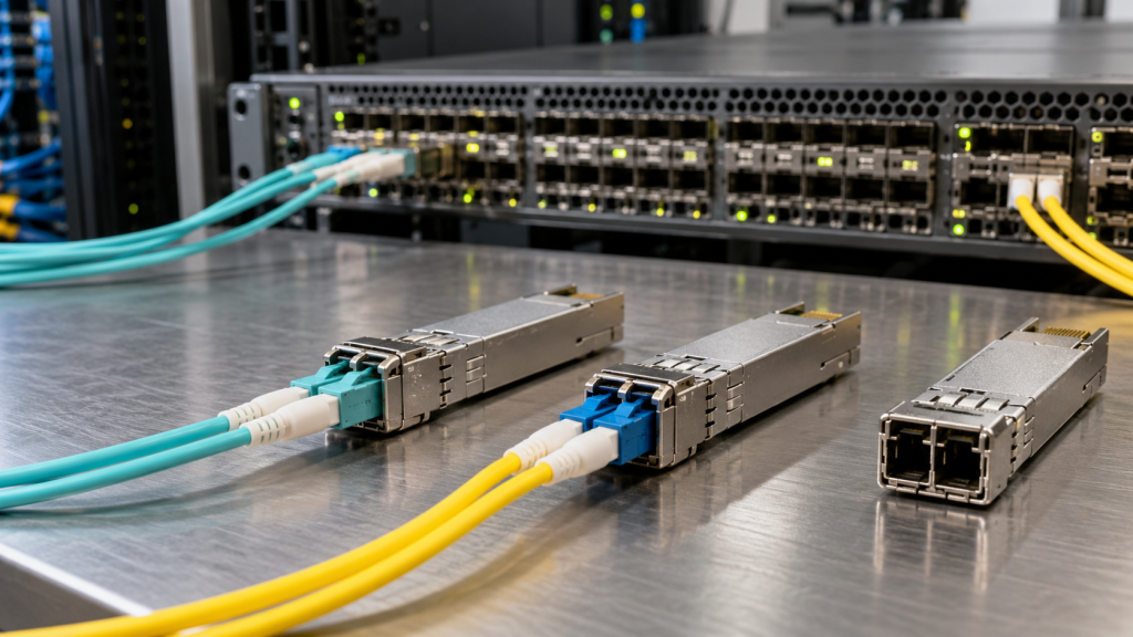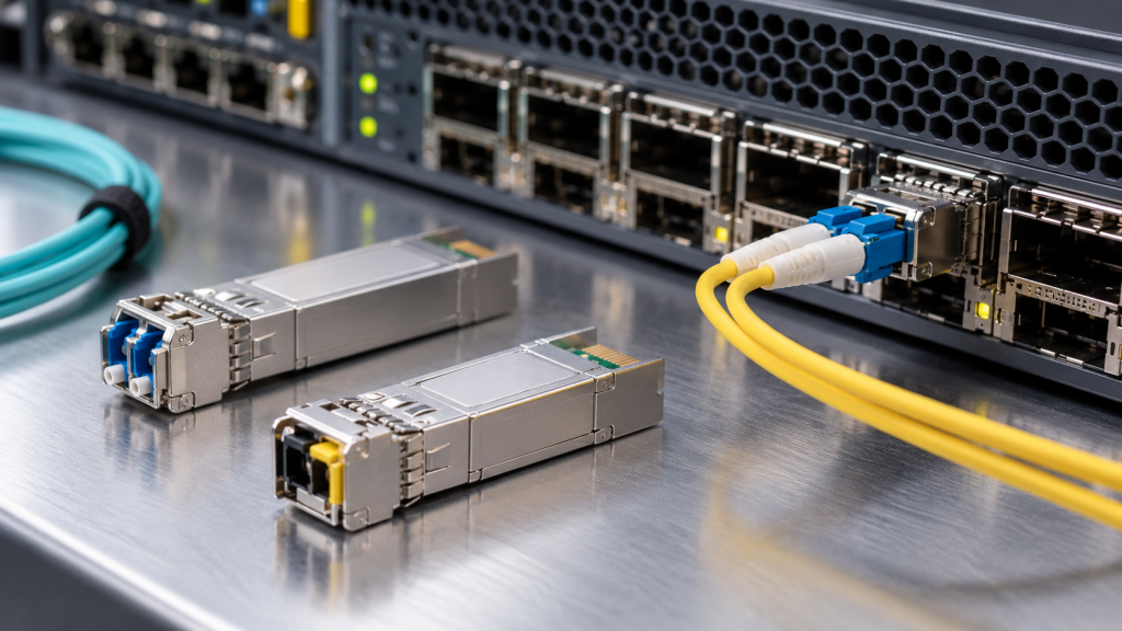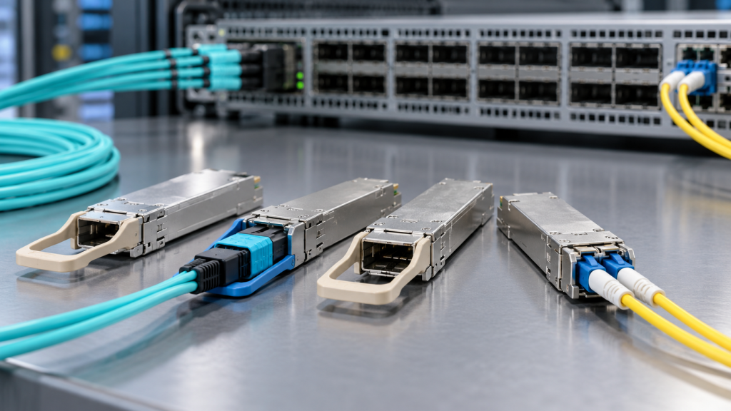
MPO polarity has one job: make sure the light leaving one switch arrives at the receiver on the other. Get it wrong and the link stays dark.
It sounds complicated because of the naming. It is not. Here is the whole thing.
The short answer
Building a 400G or 800G link with parallel optics? Use Type B. It is the only type that connects transmit to receive on its own, with no extra parts and no special patch cords.
Everything below explains why, and covers the two mistakes that cause more failures than polarity ever does.
What MPO actually is
MPO stands for multi-fibre push-on. Instead of one fibre per connector, an MPO holds 12 or 16 fibres in a single plug. That is how a 400G or 800G module carries all its channels through one cable.
Each connector has a small bump on one side called the key. When two connectors join, the key tells you which way round they are. That orientation decides where each fibre lands at the far end.
The three types
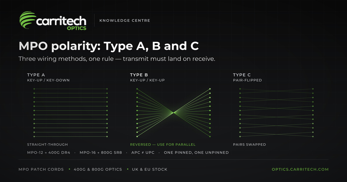
Type A — straight-through. Fibre 1 goes to position 1, fibre 2 to position 2, and so on. Simple, but on its own it connects transmit to transmit. Something else in the chain has to flip it.
Type B — reversed. Fibre 1 goes to position 12, fibre 2 to position 11, and so on. The flip is built into the cable.
Type C — pair-flipped. Fibres are swapped in pairs: 1 and 2 change places, 3 and 4 change places, and so on.
Why Type B for 400G and 800G
A 400G DR4 module sends on four fibres and receives on four fibres through one MPO-12. An 800G SR8 does the same across eight and eight through an MPO-16.
Type B’s reversal lines those up automatically. Transmit meets receive, straight out of the box.
Use Type A instead and every fibre arrives at the wrong end. You then need a specially flipped patch cord somewhere to correct it. It works — but that flipped cord is exactly the part that gets swapped for a normal one during an out-of-hours fix, taking the link down again.
Type C is mainly used for older duplex setups where two fibres carry one channel through cassettes. For parallel optics, stick with Type B.
Carritech supplies MPO and LC/SC/FC/ST patch cords alongside the optics that plug into them. Browse patch cords →
The two mistakes that break more links than polarity
Before you start tracing fibres, check these. Both take seconds and both are visible before you plug anything in.
1. Green connectors only mate with green connectors
Single-mode MPO links use APC connectors, which have an angled tip and usually a green housing. Multimode links use UPC, which is flat.
Push an angled connector against a flat one and they cannot meet properly. You get a gap, huge signal loss, and often two damaged connectors. The link will either not come up or will behave strangely.
Rule: green to green, flat to flat.
2. One side needs pins, the other needs holes
Every MPO connector either has two small guide pins sticking out, or two holes to receive them. Every join needs exactly one of each.
- Two with holes: nothing lines the fibres up. Massive loss.
- Two with pins: they will not seat, and forcing them damages the ends.
Check before you connect, and label your cables so the next person does not have to guess.
If a link will not come up
Work through it in this order — it is much faster than guessing.
1. Check the light levels at both ends. If one module is transmitting fine but the other sees nothing, the problem is in the cabling, not the modules. Our guide to spotting a failing link shows you how to read these. 2. Check green to green, flat to flat. 3. Check pins and holes. 4. Clean the connector ends. One speck of dust on an MPO can take out a single channel and leave the rest working, which shows up as odd intermittent errors rather than a clean failure. 5. Now check polarity. 6. Confirm the module type matches the cabling you have installed.
Get the whole link from one supplier
Most MPO problems come from mixing parts bought from different places, with different conventions and no documentation.
Carritech Optics supplies the modules and the cabling together, so everything arrives matched:
- [MPO and fibre patch cords](https://optics.carritech.com/optical-transceivers/patch-cords/patch-cords-lcscfcst-mpo/) in the polarity and polish type you need
- [400G transceivers](https://optics.carritech.com/optical-transceivers/400g-transceivers/) including DR4, SR8, FR4 and LR4
- [800G transceivers](https://optics.carritech.com/optical-transceivers/800g-transceivers/) in OSFP and QSFP-DD
- [DAC](https://optics.carritech.com/dac-cables/) and [AOC](https://optics.carritech.com/active-optical-cable-aoc/) for short runs where no patch panel is involved
Every optical transceiver comes with a lifetime warranty, ships from UK and EU stock, and is tested before dispatch.
Not sure what you need? Send us your switch model or an OEM part number and our team will confirm the right combination before you order. Contact us → or use the compatibility checker.
Further reading
- Choosing 400G optics: SR, DR, FR and LR
- DAC vs AOC: which one should you actually buy?
- BiDi transceivers: one fibre, two wavelengths
Standards references: connector and polarity standards come from TIA; Ethernet variants from IEEE 802.3; form factors from the QSFP-DD MSA and OSFP MSA.