Every transceiver in your network is measuring itself right now and reporting the results. Most networks never look until something has already gone down.
That is a missed opportunity, because the most common fibre failure — a connection slowly getting worse — shows warning signs weeks in advance. You just have to know which number to watch.
The short answer
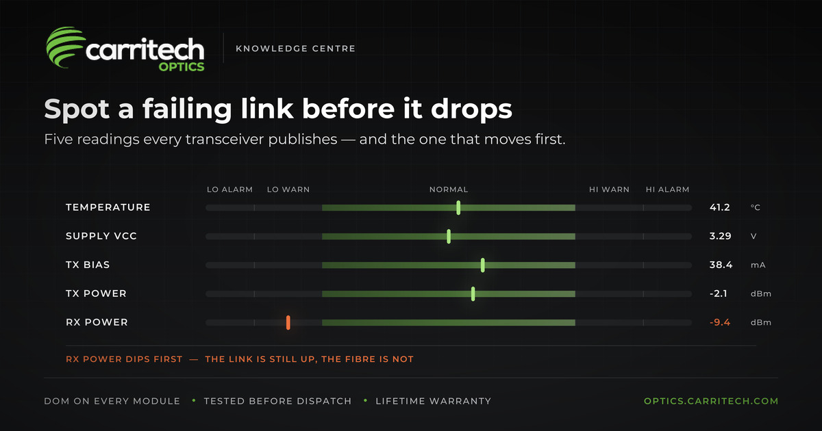
Watch receive power. It is the first reading to move when a fibre link starts degrading. If receive power is dropping at one end while the far end is still transmitting normally, your modules are fine and your cabling is not.
Set your alerts on the warning thresholds, not the alarm ones. By the time an alarm triggers, the link has already failed.
What is digital diagnostic monitoring?
Digital diagnostic monitoring — DOM, sometimes called DDM — is a feature built into virtually every modern optical transceiver. The module measures its own health and publishes the results to your switch, which can then be polled by your monitoring system.
You get five readings, and each one has a normal range plus warning and alarm limits set by the manufacturer.
Every optical transceiver Carritech supplies includes DOM as standard, from 10G SFP+ all the way up to 800G OSFP and 1.6T.
The five readings and what they mean
Receive power — how much light is arriving from the other end. *The one that matters most.* If it drops, something in the fibre path has got worse.
Transmit power — how much light this module is sending out.
Laser bias current — how hard the module is driving its laser. On its own it means little, but read alongside transmit power it tells you whether a module is wearing out.
Temperature — the module’s internal temperature, not the room. High readings usually mean an airflow problem: a blocked filter, a failed fan, or too many high-power modules packed together.
Supply voltage — normally 3.3 V. If this is out of range, the problem is your switch, not the module.
Reading them together
This is where DOM earns its keep. Four common patterns:
Receive power falling, far end transmitting normally. Your cabling. A dirty connector, a cable that has been bent too tightly, something disturbed during recent work, or a patch panel change nobody recorded. This is the classic slow failure, and it is completely visible in advance.
Transmit power falling while bias current climbs. The module is working harder to produce the same light. That is a laser wearing out. Replace it when convenient, rather than at 3am.
Temperature high and other readings slightly odd. A cooling problem. Fix the airflow, then read the numbers again — they usually settle.
Receive power at zero, far end transmitting fine. Not a slow failure but a broken path: wrong port, damaged fibre, or a polarity problem. If the link uses MPO cabling, start with our MPO polarity guide.
Three practical rules
1. Alert on warnings, not alarms. Alarm limits mark the point where the module is outside its specification. Cross one and you are already dropping traffic. Warning limits exist to give you notice — use them.
2. Record a baseline when you install. Write down the readings on day one. A link that has always shown −6.2 dBm and now shows −8.1 dBm is telling you something real, even though both figures sit inside the normal range. No threshold alert will ever catch that.
3. Do not treat DOM as a test meter. The light readings are approximate — typically accurate to within a couple of dB. That is fine for spotting change over time, but not precise enough to sign off a new fibre installation. Use a proper power meter for that. DOM tells you a link is getting worse; it does not tell you a new one was built correctly.
What to do with the readings
A simple monitoring setup that works:
- Poll all five values every few minutes. This is a slow-moving signal, so there is no need for anything more frequent.
- Alert on warning thresholds.
- Alert on drift from your installation baseline.
- Check bias current trends monthly to catch ageing modules.
- Record the readings before and after any physical work in a cabinet. Most sudden changes in receive power happen because somebody was in the rack.
Across a whole site, patterns tell you more than individual links. Receive power drifting on every module in one cabinet points at the cabinet. Temperature climbing across a row points at cooling.
Quality modules make this work
Trend monitoring only works if the readings are consistent and properly calibrated. Modules that report erratically turn the whole exercise into noise.
Diagnostic accuracy is one of the things checked on every module Carritech ships. See the 22 checks a transceiver passes before dispatch →
Why buy from Carritech Optics
- DOM as standard on every optical transceiver we supply
- Lifetime warranty on all optical transceivers
- UK and EU stock with short lead times
- Tested and coded for your platform before it ships
- Compatible with Cisco, Juniper, Arista, Nokia, Huawei, Dell, HPE and more
Browse the range: 10G · 25G · 40G · 100G · 400G · 800G · 1.6T
Replacing a module that has started to fail? Use the compatibility checker to find the Carritech equivalent of your OEM part number, or contact our team.
Further reading
- MPO polarity explained: Type A, B and C
- DAC vs AOC: which one should you actually buy?
- Optical transceiver coding and OEM compatibility
Standards references: diagnostic interfaces are defined in the SNIA SFF specifications and by the OIF; Ethernet variants by IEEE 802.3.